After checking how Mid/Side EQ affects unilateral signals (see the post), I realized that a regular minimum phase implementation of crossfeed affects signals processed with Mid/Side EQ in a way which degrades their time accuracy. I decided to fix that.
As a demonstration, let's take a look at what happens when we take a signal which exists in the left channel only and first process it with crossfeed, and then with a Mid/Side EQ filter. Our source signal is a simple Dirac pulse, attenuated by -6 dB. Since we apply digital filters only, we don't have to use more complicated measurement techniques that involve sweeps or noise. The crossfeed implementation is my usual Redline Monitor plugin by 112 dB, with the "classical" setting of 60 degrees virtual speaker angle, zero distance and no center attenuation. Then, a Mid/Side linear phase (phase-preserving) EQ applies a dip of -3 dB at 4.5 kHz with Q factor 4 to the "Mid" component only. Below I show in succession how the frequency and phase response, as well as the group delay of the signal changes for the left and the right channel.
This is the source signal:


This is what happens after we apply crossfeed. We can see that both amplitude and phase got modified, and the filter intentionally creates a group delay in order to imitate the effect of a sound wave first hitting the closer ear (this is what I call the "direct" path), and then propagating to more distant one, on the opposite side of the head (see my old post about the Redline Monitor plugin), I call this the "opposite" path:


And now, we apply Mid/Side EQ on top of it (recall that it's a dip of -3 dB at 4.5 kHz with Q factor 4 to the "Mid" component only):


Take a closer look at the right channel, especially at the group delay graph (bottom right). You can see a wiggle there which is on the order of the group delay that was applied by the crossfeed filter. Although the amplitude is down by about -22 dB at that point, this is still something we can hear, and this affects our perception of the source position, making it "fuzzier."
As I explained previously in the post on Mid/Side Equalization, changing the "Mid" and the "Side" components independently makes some artifacts being produced when we combine the M/S components in order to convert them back into L/R stereo representation. Application of the crossfeed prior to the Mid/Side equalization adds a huge impact both to the phase and to the group delay. This is because a minimum phase implementation of the crossfeed effect creates different phase shifts for the signals on the "direct" and on the "opposite" paths. To demonstrate that it's indeed due to the phase shifts from the crossfeed, let's see what happens when we instead use linear phase filters in the crossfeed section (the shape of the magnitude response is intentionally not the same as of the Redline):

This looks much better and clean. And as you can see, the filter still modifies the group delay and phase, but not across the whole spectrum. That's why I call this implementation "Almost Linear Phase." What we do here is we still apply a frequency-dependent delay to the signal, however we do it more surgically, only in the region where we do not expect any modifications done by the Mid-Side EQ part. That means, both the linear phase crossfeed and the M/S EQ filters must be developed and used together. That's exactly what I do in my evolving spatializer implementation (see Part I and Part II). As I know that in my chain the M/S equalization is only applied starting from 500 Hz (to remind you, it is used to apply diffuse-to-free field (and vice versa) compensation separately to correlated and negatively correlated parts of the signal), I developed a crossfeed filter which only applies the group delay up to that frequency point, and keeping the phase shift at 0 afterwards.
Note that 500 Hz does not actually correspond to physical properties of sound waves related to the human head size. In typical crossfeed implementations, the delay for imitating sound wave propagation is applied up to 700–1100 Hz (see publications by S. Linkwitz and J. Conover). Thus, limiting the application to lower frequencies is sort of a trade-off. However, if you recall the "philosophy" behind my approach—that we don't actually try to emulate speakers and the room, but rather try to extract the information about the recorded venue, with minimal modifications to the source signal, this trade-off makes sense.
Crossfeed Filter Modeling
One possible approach I could use to shape my crossfeed filters is to copy them from an existing implementation. However, since with linear phase filters I can control the amplitude and the phase components independently, I decided to read a bit more recent publications about head transfer function modeling. I found two excellent publications by E. Benjamin and P. Brown from Dolby Laboratories: An Experimental Verification of Localization in Two-Channel Stereo and The effect of head diffraction on stereo localization in the mid-frequency range. They explore the effect of the frequency-dependent changes of the acoustic signal as it reaches our ears, which happens due to diffraction of the sound by the head. I took these results into consideration when shaping the filter response for the opposite ear path, and also when choosing the values for the group delay.
Besides the virtual speakers angle, Redline Monitor also has the parameter called "center attenuation." This is essentially the attenuation of the Mid component in the Mid/Side representation. Thus, the same effect can be achieved by putting the MSED plugin (I covered it in the post about Mid/Side Equalization) in front of the crossfeed, and tuning the "Mid Mute" knob to the desired value (it is convenient that MSED actually uses decibels for "Mid Mute" and "Side Mute" knobs).
As for the "distance" parameter of Redline Monitor, I don't intent to use it at all. In my chain, I simulate the effect of distance with reverb. In Redline Monitor, when one sets the "distance" to anything other than 0 m, the plugin adds a combing filter. Another effect that the "distance" parameter affects is the relative level between the "direct" and the "opposite" processing paths. This makes sense, as the source which is closer to the head will be more affected by the head shadowing effect than the source far away. In fact, the aforementioned AES papers suggest that by setting ILD to high values, for example 30 dB, it is possible to create an effect of a talker being close to one of your ears (do you recall Dolby Atmos demos now?). However, since I actually want headphone sound to be perceived further from the head, I want to keep the inter-channel separation as low as possible, unless it degrades lateral positioning.
Filter Construction
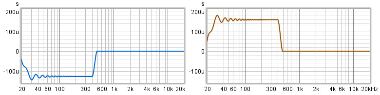
I must note that constructing an all-phase filter with a precisely specified group delay is not a trivial task. I have tried many approaches doing this "by hand" in Acourate, and ended up with using Matlab. Since it's a somewhat math-intensive topic, I will explain it in more details in a separate post. For now, let's look again at the shapes for the group delay of such a filter, for the "direct" path and the "opposite" path:

This is the filter which delays the frequencies up to 500 Hz by 160 μs (microseconds). After the constant group delay part, it quickly goes down to exactly zero, also bringing back the phase shift to 0 degrees. That's how we enable the rest of the filter to be phase preserving. Those who a bit familiar with signal processing could ask—since a constant positive group delay means that the phase shift is linearly going down, where did it start from a non-zero value in the first place? The natural restriction on any filter is that at 0 Hz frequency (sometimes this is called the "DC component") it must have either 0 or 180 degrees phase shift. What we do in order to fulfill this requirement, is we use the region from 0 to 20 Hz to build up the phase shift rapidly, and then we bring it down along the region from 20 Hz to 500 Hz (note that the frequency axis start from 2 Hz on the graphs below):

Yes, the group delay in the "ultrasound" region is a couple of milliseconds, which is an order of magnitude greater than the group delay used for crossfeed. But, since we don't hear that, it's OK.
A delaying all-pass filter is used for the "opposite" path of the crossfeed filter. For the "direct" path, we need to create an inverse filter in terms of the time delay, that means, a filter which "hastens" the group delay. This is to ensure that a mono signal (equal in the left and right channels) does not get altered significantly by our processing. Such a signal is processed by both the "direct" and the "opposite" filters, and the results are summed. If the delays in these filters are inverse of each other, the sum will have a zero group delay, otherwise it won't.
The similar constraint is applied to the frequency response. That means, if we sum the filters for the "direct" and the "opposite" channels, the resulting frequency response must be flat. This is also true for the original minimum-phase Redline filters.
So, I used the following steps in order to produce my linear phase versions of crossfeed filters using Acourate:
With help of Matlab, I have created an all-pass filter which applies a 160 µs delay between 20 and 500 Hz, and a filter which speeds up the same region by 128 µs (the reason for inexact symmetry is that the channel on the "opposite" path is attenuating). The important constraint is that the resulting group delay between paths must be between about 250–300 µs.
I created a simple sloped down amplitude response: starting from -3.3 dB at 20 Hz and ending with -9 dB at 25600 Hz, and with help from Acourate convolved it with the delaying all-pass filter—this has become the starting point for the "opposite" path filter. For the direct path, I simply took the "direct" path filter which has the needed "anti-delay" (hastening), and a flat magnitude response.
Then I applied the following steps multiple times:
Sum filters for the "direct" and the "opposite" paths. The resulting amplitude will not be flat, and now our goal is to fix that.
Create an inverse frequency response filter for the sum (Acourate creates it with a linear phase).
Convolve this inverse filter with either the filter for the "direct" or for the "opposite" path. This is a bit of an art—choosing the section of the filter to correct, and which path to apply it to. The aim is to retain a simple shape for both paths of the filter.
Below are the shapes I ended up with:

The filters that we have created can be cut to 16384 taps for the 96 kHz sampling rate. We need to keep relatively large number of taps in order to have enough resolution at low frequencies where we perform our phase manipulations.
Is There Any Difference?
After going through all these laborious steps, what improvements did we achieve over the original minimum phase filters of the Redline Monitor? First, as I've mentioned in the beginning, the main goal for me was to eliminate any phase difference between left and right channels after crossfeed processing in order to minimize artifacts from Mid/Side EQing. As we have seen in the first section of the post, this goal was achieved.
Sonically, a lot of difference can be heard even when listening to pink noise. Below is a recording where I switch between unprocessed pink noise combined from a correlated layer and an anti-correlated layer, then processed using RedLine Monitor at 60 degrees, 0 m distance, 0 dB center, and then processed with my almost linear-phase crossfeed (the track is for headphone listening, obviousl):
To me, my processing sounds more like how I hear the unprocessed version on speakers (the actual effect heavily depends on the headphones used). The noise processed by Redline has fuzzier phantom center, and there is much less enveloping on the sides. So I think, the (almost) linear phase implementation of crossfeed is sonically more accurate.