Tuesday, November 15, 2022

Long Live 16 Color Terminals

This blog entry is about the process I went through while designing my own 16 color terminal scheme, as an improvement to "Solarized light". Since I invested some time in it, I decided that I want to document it somewhere, just in case if later I will need to go back and revisit things.

What Is This All About

I need to make some introduction into terminals to ensure that I'm on the same page with readers. Terminals were one of the first ways to establish truly interactive communication between people and computers. You type a command, and the computer prints the result, or vice versa—the computer asks you "do you really want to delete this file?", and you type "y" or "n". First terminals were sort of electric typewriters—noisy and slow, thus the conversation between computers and humans was really terse. However, even then interactive text editors had become technically feasible, take a look at the "standard text editor" of UNIX—ed. Later, so called "glass terminals" (CRT monitors with keyboards) arrived, giving an opportunity to more "visual" and thus more productive interaction, and the "Editor war" had begun.

And basically, these visual terminals is what is still being emulated by all UNIX derivatives these days: the "text mode" of Linux, XTerm program, macOS Terminal app, countless 3rd party terminals, even browser-based terminals—these can run on any desktop OS. In fact, I use hterm for hosting my editor where I'm preparing this text.

As the terminal technology was evolving over time, it was becoming more sophisticated. Capabilities of teletype terminals were very basic: print a character, move the caret left or right, go to next line. "Glass terminals" enabled arbitrary cursor positioning, and then with the advent of new hardware technologies, color was added. Having that the evolution of hardware was taking time, color capabilities were developing in steps: monochrome, 8 colors, 16 colors, 256 colors, and finally these days—"truecolor" (8-bit color). Despite all the crowd excitement about the latter, I believe that "less is more," and the use a restricted color set in text-based programs still has some benefits.

Before I go into details, one thing that I would like to clarify is the difference between the number of colors that are available to programs running under a terminal emulator (console utilities, editors with text UI, etc), and the number of colors used by the terminal emulator program itself. The terminal program is in fact only limited by the color capabilities of the display. Even when a console utility outputs monochrome text, the terminal emulator can still use full color display capabilities for implementing nice-looking rendering of fonts and for displaying semi-opaque overlays—the cursor being the simplest example. Thus, setting the terminal to the 16-color mode does not mean we get back to 1980-s in terms of the quality of the picture. And unless one runs console programs that, for example attempt to display full color images using pseudo-graphic characters, or want to use gradient backgrounds, it might get unnoticed that a 16-color terminal mode is in fact being used.

Getting Solarized

I remember the trend popular among computer users of avoiding being exposed to the blue light from computer displays—maybe it is still a thing?—even Apple products offer the "Night shift" feature. Users of non-Apple products got themselves yellow-tinted "computer" glasses or were following advises to turn down the blue component in color settings of their monitors. The resulting image looks more like a page of a printed book when reading outdoors (if tuning is done sensibly, not to the point when white color becomes bright yellow), and probably makes less strain on the eyes. The same result on a terminal emulator can be achieved without any hardware tweaks by applying a popular 16-color theme called "Solarized light" by Ethan Schoonover.

I remember being hooked on the "signature" yellowish background color of this theme (glancing over shoulders of my colleagues, a lot of people are). I never liked the "dark" version because it does not look like a paper page at all. So I was setting up all my terminal emulators to use "Solarized light", and was quite happy about the result.

However, at some point I noticed that color-themed code in my Emacs editor—I run it in "non-windowed", that is, text mode under the aforementioned hterm terminal emulator—does not look like screenshots on the Ethan's page. Instead, C++ code, for example, looked like this (using some code from the Internet as an example):

I started digging down for the cause of that and discovered that every "mature" mode of Emacs basically declares 4 different color schemes: for use with 16-color terminals, and for 256- (actually, >88) color terminals, both having a version for dark and light terminal background. Sometimes, a scheme specific to 8-color terminals is also added. Below is an example from font-lock.el:

(defface font-lock-function-name-face
  '((((class color) (min-colors 88) (background light)) :foreground "Blue1")
    (((class color) (min-colors 88) (background dark))  :foreground "LightSkyBlue")
    (((class color) (min-colors 16) (background light)) :foreground "Blue")
    (((class color) (min-colors 16) (background dark))  :foreground "LightSkyBlue")
    (((class color) (min-colors 8)) :foreground "blue" :weight bold)
    (t :inverse-video t :weight bold))
  "Font Lock mode face used to highlight function names."
  :group 'font-lock-faces)

Thus, in reality in my C++ example display only foreground and background text colors are originating from the Solarized theme, and all other colors are coming from the 256-color scheme of the Emacs C++ mode. Names of colors used in this case (like "LightSkyBlue" above) come from the "X11 palette", and there are many gradations and tints to choose from for every basic color.

In fact, this is one of the drawbacks of the 256- and true-color modes (in my opinion, of course)—apps have too much control over colors, and this leads to inconsistency. For me, too much effort would be required to go over all Emacs modes that I use and ensure that their use of colors is mutually consistent. Whereas, in the 16-color mode not only apps have to use a restricted set of colors, but the set itself is in fact a terminal-controlled palette. Thus, the app only specifies the name of the color it wants to use, for example "red", and then the terminal setup defines which exact tint of red to use. So, one day I switched my terminal to only allow 16 colors, and restarted Emacs...

...And I did not like the result at all! Yes, now I could see I'm indeed using the palette of the "Solarized light" theme, but the result looks quite bleak. I took another look at the screenshots on the Ethan's page and realized that to me the colors of the Solarized palette look more engaging on a dark background. I read that the point of Ethan's design was to allow switching between dark and light backgrounds with a minimal reshuffling of colors, and still having "identical readability." However, to my eyes "readability" wasn't the same as "looking attractive."

As I tried using the Solarized light palette for doing may usual tasks in Emacs, I found that it has a couple more shortcomings. Let's look at the palette:

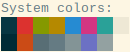
One thing that bugged me is that the orange color does not look much different from red. I can see that even with color blocks, and with text the similarity goes up to the point that when I was looking at text colored in orange, I could not stop myself from perceiving it as being in red. People are not very good at recalling how "absolute" colors look, we are much better at comparing them when they are side by side.

Another serious problem was the lack of "background" colors enough for my text highlighting needs. I'm not sure about Vim users, but in Emacs I have a lot of uses for background highlights. I can enumerate them:

  • highlighting the current line;
  • text selection;
  • the current match of interactive search;
  • all other matches of interactive search;
  • character differences in diffs (highlighted over line differences);
  • highlighting of "ours", "theirs", and patch changes in a 3-way merge;
  • and so on.

Most of those highlights must have a color on their own so they don't hide each other when I combine them, and they must not make any of text colors unreadable due to a poor contrast. As an example, if I have a colorized source code, and I'm selecting text, I still should be able to see clearly every symbol of it. This is where the Solarized palette falls short, and I can easily explain why.

Color Engineering

One of the defining features of the Solarized palette is that it was created using the Lab color space. Previously, 16 color palettes were usually assigned colors based on the mapping of the color number in the binary form: from 0000 to 1111, onto a tuple of (intensity, red, green, blue) bits, not caring too much about how the resulting colors look to users. Whereas, the Lab color space is modeled after human perception of color, and can help in achieving results which are more consistent and thus more aesthetically pleasing.

The first number in the Lab triad is the luminosity of the color. Let's look at the "official" palette definition in this model:

SOLARIZED L*A*B
--------- ----------
base03    15 -12 -12
base02    20 -12 -12
base01    45 -07 -07
base00    50 -07 -07
base0     60 -06 -03
base1     65 -05 -02
base2     92 -00  10
base3     97  00  10
yellow    60  10  65
orange    50  50  55
red       50  65  45
magenta   50  65 -05
violet    50  15 -45
blue      55 -10 -45
cyan      60 -35 -05
green     60 -20  65

We can see that most colors have luminosity in the range between 45 and 65, with only two of them having either low luminosity: base03 and base02, or high luminosity: base2 and base3. Thus, these colors are the only ones that can serve as backgrounds that work with any text color. Having that one of those 4 background colors is the actual background, only 3 remain—certainly not enough for my use case.

After considering these shortcomings, I decided to tweak the "Solarized light" palette to better suit my needs. Below is the list of my goals:

  1. Use colors that look more vivid with a light background.
  2. Make sure that no two colors look alike when used for text.
  3. Provide more background colors.

And the list of my non-goals, compared to Ethan's goals:

  1. No need to use text colors with a dark background.
  2. Can consider bold text as yet another text color.

In the design process I also used the Lab color space. Thanks to the non-goal 1., I was able to lower the minimum luminosity down to 35. I made some of the colors more vivid by increasing color intensities—as a starting point I took some of the colors used by the 256 color scheme of the C++ mode in Emacs.

In order to make the orange color to be visually different from red, I created a gradient between red and yellow, and picked up the orange tint which I was seeing as "dividing" between those two, in order to guarantee that it is the most distant tint from both red and yellow.

I decided to reduce the number of gray shades in the palette. For non-colored text, I planned to use the following monotones:

  • base1 for darker than normal text;
  • base2 for lighter than normal, less readable text, I moved it to the "bright black" position in the palette;
  • bold normal text for emphasis.

And here comes a hack! I moved the normal text color (base00 in the "Solarized light" theme) out of the palette and made it the "text color" of the terminal. Remember when I said that the terminal emulator program does not have to restrict itself to 16 colors. Most contemporary terminal emulators allow to define at least 3 additional colors which do not have to coincide with any of the colors from the primary palette: the text color, the background color, and the cursor color. The first two are used "by default" when the program running in the terminal does not make any explicit text color choice. Also, any program that does use colors can always reset the text color to this default.

Let's pause for a moment and do some accounting for colors that I have already defined in the 16 color palette:

  • 2 text colors (plus the text color in the terminal app);
  • 8 accent colors: red, orange, yellow, green, cyan, blue, magenta, and violet;
  • 1 background color (this is used when one needs to print text on a dark background, without dealing with "reverse" text attribute which usually looks like a disaster).

Thus we have 16 - 11 = 5, which means there are 5 color slots left for highlights, that's 2 more than in the "Solarized light" theme, and they are real colors, not shades of gray! Since I removed or moved away the shades of gray used by the original Colorized palette, I placed the highlights where grays used to be, as "bright" versions of corresponding colors.

When choosing color values for the highlights, I deliberately made them very bright (high value of luminosity) to make a good contrast will any color used for text. One difficulty with very bright colors is making them visually distinctive, to avoid confusing "light cyan" with "light gray" for example.

This is the palette I ended up with, and it's comparison with "Solarized light" (on the left):

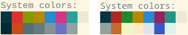
And below is the comparison of the Lab values, along with a "web color" RGB triplet. Compared to the initial table I took from the Solarized page, I have rearranged colors in the palette order:

PALETTE        SOLARIZED L*A*B       COLORIZED   HEX
-------------- --------- ----------  ----------  -------
Black          base02    20 -12 -12  20 -12 -12  #043642
Red            red       50  65  45  40  55  40  #b12621
Green          green     60 -20  65  50 -45  40  #1f892b
Yellow         yellow    60  10  65  60  10  65  #b68900
Blue           blue      55 -10 -45  55 -10 -45  #268bd2
Magenta        magenta   50  65 -05  35  50 -05  #94245c
Cyan           cyan      60 -35 -05  55 -35  00  #249482
Light Gray     base2     92  00  10  92  00  10  #eee8d6
Bright Black   base03    15 -12 -12  65 -05 -02  #93a1a1
Bright Red     orange    50  50  55  55  35  50  #c7692b
Bright Green   base01    45 -07 -07  96 -10  25  #eef9c2
Bright Yellow  base00    50 -07 -07  94  03  20  #ffeac7
Bright Blue    base0     60 -06 -03  90  00 -05  #dfe3ec
Bright Magenta violet    50  15 -45  40  20 -65  #3657cb
Bright Cyan    base1     65 -05 -02  94 -08  00  #ddf3ed
White          base3     97  00  10  97  00  10  #fdf6e4
Text Color                           50 -07 -07  #657b83
Cursor Color                     Bright Magenta, opacity 40%

(Note that even for colors that retain their Lab values from Solarized, I may have provided slightly different RGB values compared to those you can find on Ethan's page. This could be due to small discrepancies in color profiles used for conversion, and unlikely produce noticeable differences.)

Compared to the "Solarized light" palette, I have redefined 6 accent colors, and thrown away 2 "base" colors. I decided to name my palette "Colorized," both as a nod to "Solarized" which it is based on, and as a reference to the fact that it looks more colorful than its parent.

Emacs Customizations

Besides defining my own palette, I also had to make some tweaks in Emacs in order to use it to full extent. While customizing colors of the C/C++ mode, I made it visually similar to the 256 color scheme I was using before, but more well-tempered:

Shell Mode

It's a well known trick to enable interpretation of ANSI escape sequences for setting color in the "shell" mode of Emacs:

(require 'ansi-color)
(add-hook 'shell-mode-hook 'ansi-color-for-comint-mode-on)

What is less known is that we can then properly advertise this ability to terminal applications via the TERM variable by setting it to dumb-emacs-ansi. This is a valid termcap / terminfo entry, you can find it in the official terminfo source from the ncurses package.

Besides that, it's also possible to map these ANSI color sequences to terminal colors arbitrarily. For example, I mapped "bright" colors onto bold text. This comes handy both for the original Solarized palette and my Colorized one because "bright" colors in it are in reality not bright versions of the first 8 colors, thus when apps try using them the resulting output looks unreadable.

The full list of Emacs customizations is in this setup file. It's awesome that when using it, I naturally forget that only 16 colors (OK, to be fair, 17, if you recall the terminal text color hack) are used. This way, I have proven to myself that use of "true color", or even 256 color terminal is not required for achieving good looks of terminal applications.

Conclusion

Big kudos to Ethan Schoonover for creating the original Solarized theme and explaining the rationale behind it. The theme is minimalist yet attractive, and proves that it's possible to achieve more with less.

Monday, September 5, 2022

MOTU: Multichannel Volume Control

Going beyond simple 2-channel volume control still presents a challenge, unfortunately. The traditional design is to view a multichannel audio interface as a group of multiple stereo outputs, and provide an independent volume control for each group, without an option to "gang" multiple outputs together. True multichannel output devices are normally associated with A/V playback, and indeed modern AVRs do present flexible options for controlling the volume, including support even for active crossovers. For example, the Marantz AV7704 which I was using for some time has this option. However, AVRs usually have a large footprint in terms of consumed space.

Computer-based solutions are even more flexible, and in recent years come in compact forms and fanless cases, making them a more attractive alternative to AVRs. I was using a PC running AcourateConvolver also for a long time. I didn't mind that it applies attenuation in the digital domain, because it does that correctly, with a proper dithering. However, Windows does not appear as a hassle-free platform to me, because it always unceremoniously wants to update itself and restart exactly when you don't want it to do so.

After the Windows computer which I was using for AcourateConvolver broke, the solution I had switched to was RCU-VCA6A by RDL (Radio Design Labs), which seems to work reliably, does not want to update itself, and does not introduce any audible degradation into the audio path (at least, compared to the VCA built into the QSC amplifier). But still, it's an extra analog unit, could we get rid of it?

Turns out, the solution was right there all the time since I started my audio electronics hobby. It can be trivially done using ingenious control software of "MOTU Pro Audio" line of audio interfaces, which includes my MOTU Ultralite AVB. Interestingly, the first thing that I had noticed when I bought this audio interface is that the control app runs in the browser, talking to the web server running on the card. This was in a sharp contrast to the traditional approach to install native apps on the host Mac or PC.

What I failed to realize, though, is that the control app actually has two layers. There is the visible UI part, but also the invisible server which provides a tree-like list of the audio card resources. Thus, in order to automate anything related to the audio interface management there is no need to work "through" the web app, it's allowed to talk to the server part directly. This is great, because any automation which tries to manipulate the UI is fragile by definition.

I've found the reference manual for MOTU's AVB Datastore API, which is indeed very simple, and any CLI web client can work with it. Another useful fact that I have discovered by accident is that although the datastore server reports the range of accepted values for the trim level of analog outputs 1–6 being only from -24 dB to 0 dB, it happily accepts lower values, thus the effective trim level of all analog outputs is the same, going down to -127 dB.

I decided to re-purpose some of the physical controls on the card itself to serve my needs. Since I have a dedicated headphone amplifier, I never use the phones output, thus the rotary knob and the associated trim level for the phones output can instead be used to control the trim level of the analog outputs. When turning the knob, the current volume level is displayed on the audio interfaces' LCD screen. This is needed because the knob is just a rotary encoder, not a real attenuator, thus it does not have an association between the current level and the knob's position. This fact actually makes it much less comfortable than the VCA volume pot which I've made myself to use with RCU-VCA6A. With the encoder it's convenient to perform small adjustments—a couple of dBs up or down, but turning the volume all the way down requires too many turns. Thus, I also wanted to have a mute button. I decided that since I never have used the second mic input, I can use it's "Pad" button to fulfil this role. The "Pad" button has a state, and it's lit when it's turned on.

In order to implement these ideas, I had to write a script. I decided not to use Python to avoid over-designing the solution, instead I turned to something really simple, stemming from the original UNIX systems of 70-s—a bash script. In fact, this solution is truly portable as the POSIX subsystem is part of any modern operating system, including even Windows (via WSL).

The logic of the script is simple. I use the volume of the phones output as the source value for all analog outputs driving my desktop speakers: outputs 1–5. The volume of the output 6 is used to store the mute level. Thus, in practice it can be a full mute, or it can be just a "dim" (for example, -40 dB). The value of the pad for Mic 2, as I've mentioned before, is used to switch between normal and mute trim levels. This way, the control logic can be described as follows:

  1. Read the current values of the "main" and "mute" trims, and the value of the mute toggle switch.
  2. Depending on whether the device is supposed to be muted according to the switch, swap the values as needed.
  3. Apply the volume to the analog outputs.

Then the script uses the ETag polling technique to ask the server to report back when any of the values have changed as a result of user's action (this is also described in MOTU's manual). Then all goes back to the start.

The full script code is here on GitHub, it's only about 70 lines of code. If needed, this way of controlling the MOTU interface can be extended to be fully remote.

Sunday, August 14, 2022

Modular Audio Processing System, Part III

Finally, after Part I and Part II, we are getting to the last part of my audio system description. First I'll tell a few words about the power unit, and then get into details about iterating on the digital audio path, also presenting some measurments.

The Power Unit

When there is a bunch of hardware units stacked in a rack and each of them requiring a power outlet, a natural desire occurs to have only a single power cord for the entire rack. For a long time a was using a simple metal-housed power strip which I bolted on the side wall of the rack. At some point I decided that I want to provide a more serious level of protection for the equipment. I also wanted the power unit to be implemented in the same half-rack form-factor as the rest of the equipment, and of course I wanted it to have no fans.

Around that time I also learned about the principle with a somewhat spiritually sounding name—the principle of "non-sacrificial" power protection. There is nothing supernatural in it though. Most power filter and protector strips used at home employ electrical elements that are intended to take the impact of an electrical power surge and thus "sacrifice" themselves, protecting the equipment this way. The elements used for this noble role are called "metal oxide varistor" (MOV). The problem is that power protectors never indicate how many MOVs contained in them are still in a good shape, thus it's always a lottery when such a protector will fail, possibly taking down the downstream equipment with it.

Whereas, the power protector I've bought: Middle Atlantic PD-415R-SP was intentionally built using a MOV-free design. Another feature advertised by the manufacturer is EMI filtering between the sockets, which is nice to have, at least in theory, when one has to mix digital and analog equipment and use switched power supplies. I must admit, I partially defeated the last feature by using power socket splitters, because the power unit unfortunately only has 4 sockets, while I have 7 pieces of equipment to power. However, since there is a lot of equipment and wires packed into a compact rack, there is a lot of EMI "flying" around, thus filtering just at connection points is not enough anyway.

To close the topic on the power unit, another its drawback besides not having enough sockets is relatively high price—around $350–$500, depending on the dealer. However, if we divide this price per socket, and compare to the price of equipment it protects, it seems like a reasonable investment.

The Digital Path

Finally, the fun part. My aim was to ensure that practically any digital source of audio could be connected to the input of the DSP. This is because I don't want to limit myself to use of certain streaming services or stick to media software like Roon. I'm a long time Google Play / YouTube Music user, I ripped my audio CDs, I also might want to play something via a browser. In addition, recently I decided to subscribe to Apple Music because they have switched to lossless streaming, and even offer "high resolution" versions for many popular albums—with a monthly fee which is less than a cost of a typical CD this was an easy decision.

In order to be able to use wide variety of software-based audio sources, one needs to use a real computer, or at least a mobile device. Initially I tried using the same Mac Mini which runs my DSP, however the performance of this 8-year old machine is clearly not enough to avoid glitches when running a browser alongside Reaper. Also I realized that I want a device with its own screen and keyboard input, so I can use it while I work. So I took off a shelf an old MacBook Air which I connected directly to the MOTU card by Ethernet via the AVB protocol. After a short period of use it has become obvious that modern browsers can pose a heavy load for any old computer—after half an hour of streaming YouTube Music the MacBook Air was always turning its fan on and ruining the listening experience.

I firmly decided that I need a fanless device, so I restored another "Air" device—this time an iPad Air—it had its screen broken and I worked around this with a help of an adhesive "screen protector" film. Then I started considering options for getting digital audio out the iPad (mine has a 3.5 mm analog output, but...) and I realized there are plenty of ways:

  • AirPlay, which can be used either over wireless or over wired network connection. Since iPad needs to be connected to a charger, the wired option seems to be more appropriate, especially if an Ethernet dongle with PoE (Power-over-Ethernet) is used—just a single wire needs to go into the device!

  • HDMI output via a dongle—since it's an old iPad model, it has a Lightning output, thus use of an Apple-made dongle is preferred.

  • USB output via a different type of dongle. Obviously, this dongle needs a power input, too. Unfortunately, USB audio interfaces that can provide power are less frequent to encounter than I would like.

Let's compare these options more thoroughly.

Comparison of Digital Output Alternatives for iPad

AirPlay

The AirPlay protocol—it's not a secret that it is based on an open RTSP streaming protocol, and once the encryption key that Apple uses was extracted, there are now plenty of open-source clients. I have a Raspberry Pi lying around (naturally, I amassed a lot of old computing devices), and I found the DigiOne SPDIF "hat" for RPi from a company that seems to care about audio quality—Allo.com. Another option is to connect Pi to an USB Audio Class compliant sound card.

I decided to try shairport-sync AirPlay client. After going through its docs I have realized that unlike the AVB protocol, AirPlay does not have a notion of "master clock," which means that the sender and the receiver of audio essentially run "freewheleed." Thus, even if both use the same nominal sampling rate (the AirPlay protocol always uses 44.1 kHz sampling rate), due to difference between the effective sampling rates (for example, the ends up running at 44099 Hz and the receiver at 44101 Hz), frames can be dropped or zero frames needs to be stuffed into the stream, thus glitches are unavoidable without a special precaution. In order to avoid glitches shairport-sync resamples the received audio to the sampling rate of the playback device. The effective sampling rate of the sender is discovered from timestamps sent together with audio data.

After playing with shair-port sync, I must admit that I'm impressed with the efforts of its author Mike Brady to make a software that "just works." However, since I didn't really have to transport audio far away and over wireless networks, I decided that perhaps all this complexity of re-synchronization at the receiver side can be avoided. Another important shortcoming of shairport-sync is that it only supports sampling rates that are multiples of 44.1 kHz, and according to this answer by Mike use of other base rate (that is, 48 kHz) is not possible without a substantial rework of the software.

HDMI

The second option was to use HDMI output. I dismissed HDMI on the grounds that I only need a stereo output, have no interest in multichannel encoded content. Also, use of HDMI has some additional shortcomings:

  • iOS always uses 48 kHz sampling rate (at least, with the HDMI audio splitter that I have), which enforces resampling at playback time of all the content that Apple Music offers: the majority of albums on Music use 44.1 kHz sampling rate (so far I've only encountered one album in 48 kHz, it was "Waiting for Cousteau" by J.M. Jarre). The "Hi-Res" content uses either 96 kHz or 192 kHz. Note that Apple Music may still display a "Hi-Res Lossless" logo while resampling the "Hi-Res" content down to 48 kHz, which is clearly misleading.

  • No volume control on the digital side. Since iPad assumes it plays on some TV or an AVR which offers its own volume control, it always outputs at digital full scale. This obviously leads to clipping of intersample peaks.

  • iPad bears extra load because it also streams its screen along with the audio signal. The HDMI dongle gets warm pretty fast, too.

Thus, use of HDMI output is not an optimal solution for my scenario. This leaves us with the USB output option via "camera kit."

Dealing with USB Output Reliability Issues

The camera kit has a fat ugly wire which goes into iPad, and needs two incoming wires: one for the USB device, and one for power. I really wanted to hide the dongle inside the equipment rack and started looking for a Lightning extender. This has revealed an interesting fact—there exist no "MFi certified" (that is, approved by Apple) Lightning extenders. The extenders which claim to be "certified" are absent from the Apple's database. Apple does not make them either, nor does Belkin (the only accessories manufacturer which I would trust). Nevertheless, I still tried to use an extender wire which at least was shielded (a lot of extenders sold on Amazon are not even shielded, making them suitable only for charging purposes), and it was mostly working, except when it didn't. From time to time Apple Music was stopping playing in the middle of a song—the playback was still "going" on the screen, but there was no sound until the next song.

Finding the source of instability turned out to be a challenging task. Besides trying different Lightning extender wires I also tried 3 different USB transports: Douk Audio U2 Pro, Xing AF200, and finally RME FireFace. None of them were working reliably, including FireFace, and this was really suspicious, knowing that RME is usually rock-solid. Luckily, RME provides an iOS app which allows checking the state of the audio card mixer, and there I could see that whenever audio stops playing, it actually just stops coming from the software, despite the fact that the software (for example, Apple Music) was happily showing that it is playing. Also, while configuring FireFace to work as a USB Audio Class device, I have read some insightful information in its manual regarding connection to Apple devices. RME strongly recommends connecting the USB dongle to any Apple device directly. Finally, this is how I ended up connecting my dongle, and this has solved the stability problem for all USB transports I used.

I chose Xing as my USB transport because it has a screen which shows the current sample rate, attenuation, and playback state. Also, it offers the best variety of digital outputs, including an AES3 balanced digital output which I connected to the input of the sample rate converter.

Power Sources for iPad and Xing AF200

I need to mention that the difficulty with finding the source of iPad's playback instability was exacerbated by the need to find the right power supply for it and for the USB transport. I thought I could just plug the iPad into any USB power outlet and be done with it. However, life is not so easy. First, iPad is picky about power sources—there are various proprietary charging protocols used by Apple, and apparently iPad has some expectations. Obviously, Apple's own charger is accepted, however I've found that it creates a voltage offset between the ground of the output signal and the power ground.

The voltage offset results from a combination of unwanted AC and DC voltages. The AC part is usually some kind of harmonics of the 60 Hz from the power outlet or oscillations produced by the conversion circuitry. Having an offset (either DC or AC) is undesirable because if the USB transport is powered from the same charger, this offset is propagated to the "ground" wire of any electrical unbalanced output, and this can easily cause instability in reception on the input side.

I tried Anker PowerPort 6 charging unit, however its output offset from the power ground is just enormous, around 37V, and this is clearly problematic. I guess, nobody at Anker was envisioning use of this charger in an AV setup.

Finally, I ended up using one of USB ports on the Mac Mini. iPad had no problem charging itself from this port, and it has no significant voltage offset. However, its output power is limited, and I have to power both the iPad and the USB transport. Luckily, the Xing USB transport can also accept an external DC power input, thus leaving USB connection for data transfer only. Unfortunately, it can not send power to iPad. If only it could do that it would obviate the need for an extra USB power wire.

Since all these wires going back and forth and making loops between devices can easily become sources of noise voltages due to ground potentials difference, when choosing a power supply for Xing AF200, I was looking for something flexible. Thankfully, Allo.com has covered that as well, offering an excellent 5V low-noise power supply called "Nirvana" which offers a "ground lift" switch for the DC output, as well as a ground connector. Thus, one can always configure it in a way which eliminates difference in ground potentials.

Later I found that a powered USB hub by Amazon Basics is also properly engineered to have only a negligible voltage offset on its USB outputs (relative to the power ground), however it's not as flexible as Nirvana SMPS. All in all, the resulting connection scheme looks like this:

Needless to say, after all these adventures I'm not a big fan of consumer digital audio equipment. Although I have found a stable configuration, it still feels a bit fragile, for example, once I tried to use a different USB-A/C cable between the "camera kit" dongle and Xing, and this immediately had broken the stability of playback. Apparently, consumer-grade equipment is not designed for use in complex AV systems.

Mutec MC-6 Sample Rate Converter

A quick note on the company name: please don't confuse "Mutec" with "Mytek"—company with a similarly sounding name which also makes audio equipment.

In the world where each digital device is capable of doing sample rate conversion, and the state of modern software converters is really good, why one would still need to use a hardware sample rate converter? For me, this is just a matter of convenience. The MC-6 unit has 4 inputs of various formats: AES3 (balanced XLR), AES3id (BNC), SPDIF (RCA), and TOSLink (optical), as well as the same outputs, plus BNC ins and outs for word clock. In normal SRC mode, only one of the inputs is active. The ability to choose among multiple inputs places the MC-6 unit into the same role which a pre-amp plays in "classic" hi-fi setups.

I also need to mention that the unit is perfectly engineered—switching between inputs and locking onto the source, as well as losing sync if the source gets disconnected does not cause any audible pops. Unlike consumer devices like iPads this unit is built for a constant 24/7 use and works absolutely reliably. I prefer to use XLR and TOSLink ports because they have a good tolerance for surrounding EMI and differences between ground potentials of units. As we have seen in the section about power sources, use of consumer-oriented power supplies can easily result in huge voltage offsets.

Regarding the clipping of oversampling peaks——this is something I always try to prevent because I often listen to recordings which accidentally or deliberatly leave no digital headroom. Unfortunately, MC-6 does not provide any headroom, it's not really possible with digital-to-digital conversion done in the integer domain—thus, it clips intersample peaks. Being aware of that, in order to avoid clipping on albums that are mastered without any digital headroom I use attenuation on the USB transport (Xing). I usually set it to -4 dB, switching to unattenuated output for classical recordings which are usually mastered the right way.

Measurements

Measuring digital paths is trickier than analog ones. In order to look at digital signal in analog domain, which can reveal issues with cables, one needs a wide bandwidth oscilloscope—I don't have it. Another "classical" test is the J-Test, which can reveal issues in digital paths by looking purely from the digital side. The idea of J-Test is that it creates certain pattern of bits which can provoke unwanted modulations in the digital signal while it's being transmitted. These bit patterns are specific to the sampling rate being used. Thus, when a sampling rate converter is inserted, these bit patters do not really work as intended when we look at the output from the converter.

I decided to apply a different approach. For sampling rate converters, there is a set of tests proposed by the Infinite Wave team which evaluates how well low-pass filters of the converter suppress aliased frequencies, and also characterizes the properties of the filters. As it can be seen from the results page, the primary application of tests is for software sample rate converters. Hardware implementation can introduce more nonlinearity, and also can have "imperfect" effective sample rates, deviating from the nominal sample rate. Thus, in addition to the tests done by Infinite Wave I also did THD measurements using Acourate.

Since the team at Infinite Wave uses specialized software, I investigated how can I make similar tests using Audacity and REW. I used a regular log sweep for checking aliases using the Spectral analysis in REW. Note that the measurement log sweep has a regular frequency change rate, compared to a more specialized sweep used by Infinite Wave. This explains the difference in curve shapes, while the idea of the test is preserved. And for characterizing the low pass filter I simply passed a Dirac pulse via the chain. Since the chain is digital, we have a transfer system which is very close to textbook.

My primary interest was to check what is happening to a digital signal played at 44.1 kHz from iPad while it is passing through my digital equipment chain to the MOTU interface which runs DSP at 96 kHz sampling rate. I also tried sending test signals via AirPort to the Rasperry Pi equipped with a DigiOne SPDIF "hat" and running shairport-sync.

Below is the diagram of both chains. It demonstrates similarities between them and shows differences. The difference in the resulting sampling rates: 96 kHz vs. 88.2 kHz can be ignored. Note that I used a wired Ethernet connection between iPad and Raspberry Pi in order to avoid possible packet losses over WiFi. It was the same iPad in both cases, and I used VLC to play test signals.

Mutec MC-6

Let's start with the impulse response of MC-6 which was obtained by passing a Dirac pulse through it:

We can see that MC-6 uses a linear phase low-pass filter. Let's look at its passband and transition bands (this is the same frequency response graph, just framed differently):

We can see that the response is flat up to 20 kHz, then it abruptly goes down, essentially trimming out everything past 24 kHz. I suppose, the ripples on the passband graph are artefacts of REW's own processing. Note two interesting moments:

  • The low pass filter does not attenuate sufficiently frequencies in the region from 22 kHz to about 23.5 kHz. I think, this is an engineering trade-off to limit pre-ringing.

  • The phase does not stay flat and lags, which I find surprising for a linear phase filter. I will dig deeper into the reason behind this, it can be caused by REW processing, or it can be actual lag due to asynchronous sample rate conversion.

After figuring out the time- and frequency-domain properties of the filter we can now explain the spectrogram of a log sweep:

We can see that near the end there is some aliasing. I can explain that by the fact that aliases that have appeared after converting from 44.1 kHz were not sufficiently attenuated by the low pass filter. I think the approach to filtering used by MC-6 is similar to "allow aliasing" option of the sample rate converter of the SoX toolkit.

Finally, let's look at the distortion for a 1 kHz sine wave. Below are graphs for the sine at -0.1 dBFS and -60 dBFS:

We can see that the -60 dBFS is very clean, whereas the "almost full scale" wave exhibits some non-linearity. As we can see, even digital paths are not completely free from level-dependent non-linearities. However, measured distortion and noise levels are far below audibility thresholds:

And just to confirm to myself that my choice of the protocols and equipment used for the digital audio path was correct, I made a couple of measurements of the AirPort path via shairport-sync running on Raspberry Pi (recall the diagram above).

AirPlay via shairport-sync

After I have looked a the waveform of the recorded logsweep as it was produced by shairport-sync I already got some doubts:

Note spurious "hairs" above the 0.5 mark—those were not present in the original signal, as the entire sweep is at -6 dBFS (that's 0.5 on this scale). We can see that the frequency response graph is also rather jaggy:

Unsurprisingly, the spectrogram of the sweep shows a lot of artifacts as well:

Note that shairport-sync was built with support for resampling via SoX, and I have enabled it in the config file. Just to make sure that the rest of the chain (Raspberry Pi, DigiOne, and RME FireFace) works correctly, I pushed the same logsweep file onto Raspberry Pi, and played it using SoX, also with resampling—and there were no artifacts on the recorded sine wave and on the spectrogram. That means, the artifacts we see with shairport-sync are caused either by the AirPlay protocol itself (maybe, it's not actually lossless after all?), or resynchronization done by shairport-sync. In any case, this has confirmed that my choice of using digital output over USB was the right one.

Conclusions

Building an audio processing and playback chain is not a trivial task even when using off-the shelf components completely. It's not only the performance of each individual component that matters, but also the way they are connected together. Even in a chain where audio is transmitted predominantly via digital paths, these can still be non-linear effects and losses of the signal. To my opinion, this illustrates very well the idea which Rod Elliott has expressed in his article, that "digital" is just an abstraction—a very powerful one, but still an abstraction, and that "analog" aspects like voltages and currents must nevertheless always be taken into account.

Wednesday, June 29, 2022

Modular Audio Processing System, Part II

I have finished my last post about my audio system with a promise to tell about its digital part and the power supply. However, since that time I've already managed to do some changes to the analog part. The changes were caused by my intent to swap the KRK monitors for something that has less distortion. This has turned to be a project on its own—a conversion of a pair of LXmini speakers into a desktop version, and re-tuning them to have lower distortion. The conversion is a topic for some future post, while the topic of this post is about integrating the 4 channel QSC amplifier into the system and comparison of volume control circuits used by the amplifier and the RDL RU-VCA6A unit.

I use QSC SPA4-100 for driving speakers in LXmini. You might recall that LXmini uses "active crossover" approach and some DSP in order to turn a 4" midrange driver into a full range (albeit bass limited) dipole. One interesting aspect of the SPA line of amplifiers by QSC is that they have some "pro" features like the ability to drive 70V/100V long-range lines, and be remotely controlled. The remote control includes volume adjustment via a 10k variable resistor (pot). This appeared to be interesting to me because with this volume control I could bypass the need to use the RDL RU-VCA6A and connect the amplifier to the output of the sound card directly. It was still needed to retain the RDL control for the subwoofer though, thus the question was—is it possible to use the same gual ganged volume control pot both for RDL and QSC units, and will this work as expected.

The 10k Pot "Interface"

There is an unpublished standard for professional amplifiers and home installations to use a 10 kOhm linear taper potentiometer to control voltage. The conrol line uses 3 wires: ground, full scale DC voltage, and attenuated voltage. This naturally corresponds to the 3 posts of a variable resistor. DC voltage used by control circuits can be as high as 10 VDC, which is in fact what SPA4-100 uses, although the current is only 12 mA, whereas RU-VCA6A uses 5 VDC at 50 mA as a control signal,

You can often find potentiometer assemblies ready for in-wall or in-rack installation for ridiculous prices around $50. There is no real need to buy them, because there is absolutely nothing special in these potentiometers. They don't have to be linear—I use a logarithmic pot and even find it more convenient because I can quickly lower the volume and have a finer control at the "louder" end.

The input is thus a "standard." Yet, since it's not a real standard, manufacturers of amplifier and VCA units are free to choose how control voltage values map to gain or attenuation applied. Recall that VCA units typically have no gain on their own—a unity gain (0 dB or 1.0 multiplier), they can only attenuate the incoming line level signal. While in amplifiers with gain control there is a stage with fixed gain, for example 20 dB, and the gain control is implemented as a VCA feeding that stage. The maximum gain on amplifiers, which corresponds to unity gain on VCA units maps to the zero resistance position on the controlling pot—the maximum value of controlling voltage. This is where the agreement between manufacturers practically ends. What happens as you start turning down the controlling pot, thus increasing its resistance and decreasing the controlling voltage, purely depends on the intentions of the unit manufacturer. As I've learned, QSC and Radio Design Labs (RDL) see it in very different ways.

Volume Curves

In order to obtain a complete picture of SPA4-100 and RU-VCA6A behavior, I have traced gain changes corresponding to controlling voltage changes. The resulting function is known as a "volume curve." I used two multimeters by Agilent, both connected to a PC via a data logger. One multimeter logs the current resistance of the pot, the other logs the voltage of the audio output from the unit:

Agilent can display dBV levels by itself. Thus, by feeding the device under test with a sinewave at the reference level of 0 dBV, the reading of the multimeter on the output provides the device's gain directly. Then we can use log timestamps in order to establish correspondence between the controlling voltage and resulting gain. Note that because both the amplifier and the VCA unit accept balanced input, feeding them with unbalanced input—and that was what I did—decreases measured gain by half, that is by 6 dB. This is not relevant to the experiment because our intent is to measure both devices under the same conditions and compare their volume curves.

Using the approach above, I established that the amplifier goes from +24 dB down to -60 dB of gain, while the VCA unit goes from -6 dB down to -90 dB. Thus, the range of applied gains is actually similar, and is around 84 dB. However, the volume curves are totally different. In order to compare them, I've "normalized" the gain of the VCA unit, as if it were connected to a 30 dB fixed gain amplifier. Let's look at the shapes of the curves:

We can see that the volume of RU-VCA6A has a uniform slope (various bumps on it are likely due to imperfections in my measurement setup), whereas the volume curve of SPA4-100 has a linear region in the beginning up to about 2.5 kOhm resistance of the controlling pot, then it starts sloping, albeit slower than the curve of the VCA unit, and then at about 8 kOhm the amplifier basically drops the gain to the floor value of -60 dB.

Thus, it's not possible to achieve synchronous gain when using the same controlling pot for both devices. The fact that the VCA unit which controls the sub, lowers the gain at a faster pace than the amplifier for the main speakers leaves no hope to use nonlinearity of hearing—equal loudness curves—because they work exactly in the opposite way. And then I found yet another problem...

Noise and Distortion of the QSC VCA

As I started experimenting with the volume control on the QSC amplifier, I noticed that although the setup has practically no audible noise at the highest volume, the noise becomes audible as soon as I start turning the volume down. Normally, a power amplifier amplifies any noise fed to its input, and the higher the gain, the louder that noise will sound. The absence of noise at the highest volume proves that the noise from the DAC output is negligible low. Why does the noise starts appearing as we are making the gain lower?

I took some measurements of noise alone and of THD+N to demonstrate this phenomenon:

The blue FFT is taken at 2.5 kOhm, and the green FFT is at 3 kOhm of the controlling resistor value. The increase in noise and distortion is substantial and can be heard easily.

Now, looking at the volume curve of the amplifier, I've got the idea where does the noise comes from—it's from the amplifier's VCA unit which apparently has lower quality than the constant gain part. It seems that the VCA unit is bypassed when there is no attenuation. This explains the presence of the horizontal part on the volume curve. Once the volume control passes certain point, the VCA is engaged and the noise from it kicks in.

I guess, this was some sort of an engineering tradeoff. Understanding that not everyone really needs a volume control on a power amplifier, engineers at QSC provided a lower quality solution to save some money, however they were smart enough to get this lower quality VCA part out of the way on the critical path.

The Final Arrangement

Now for completeness, this is how my modular system looks after installing the QSC amplifier:

And this is the updated diagram of component connections:

Next time, I will finish this trilogy with a story about the digital part of the chain.

Saturday, March 26, 2022

Modular Audio Processing System, Part I

Recently I have completed assembling a system which I use for my casual audio playback needs and for audio experiments. I decided to reflect on the process of choosing and tuning the components of the system, also mentioning other options I was considering.

The goal of the system is to accept audio from various sources: files, mobile devices, web browsers, then process it to apply necessary room/speaker correction and binaural rendering, and then play on speakers and on headphones. There are of course numerous ready made commercial solutions for this, packing everything into one unit, however my intention was to have a truly modular system where each component can be replaced, and new functionality can be added if needed. Essentially, the system is built around a Mac computer with a pro soundcard. The challenging part was to figure out what additional equipment I need, and how to organize it physically, so that it does not just lay as a pile on the table, entangled by a web of cables.

For a long time already I stick to the "half rack" (9.5 inches) equipment form factor. I have a couple of racks and some audio equipment which either was designed for this format, or can be easily adapted to it. Here is how my current rack looks like:

Below is the schematics of connections between the blocks:

As I've mentioned before, the heart of the system is a Mac—an old model Mini from 2014, which I'm also using to type this post in. I've highlighted the inputs and the outputs of the system. Some of the input and output ports are mounted on the back panel:

All other interconnections are hidden inside the rack, and this makes the result to look nice if not "professional." Now let's consider the system component by component.

Mac Mini + MOTU UltraLite AVB

These two components essentially make a single unit equivalent to a dedicated DSP system, but in my opinion, more flexible. I wrote about the capabilities of UltraLite before: here and here. The features that I use for my needs are:

  • The routing matrix which is convenient for collecting various inputs: from applications, from external hardware, and via Ethernet. Note that I only use digital inputs on UltraLite in order to avoid adding noise.
  • AVB I/O is worth mentioning on its own as, I think, it's much more flexible than traditional point-to-point digital audio interfaces: SPDIF and USB.
  • DSP with some basic EQ functionality, as I wrote in the earlier post on the speaker system setup, it's enough for some basic corrections, however it is incapable of "serious" linear phase processing, which is done on Mac.

As for the functionality where UltraLite falls short, Reaper DAW running on Mac Mini helps to fill in the gaps. Here I can run linear phase FIR filters, linear phase equalizers, crossfeed and reverberation for headphones, and create arbitrary audio delays for synchronizing audio outputs. Note that although Mac Mini isn't a fanless computer, it stays perfectly quiet while running all this processing. Only sometimes does it briefly turn on the fan—this sounds like a loud exhale—and then keeps itself silent for awhile.

Having AVB input is nice as it allows using other computers for providing audio. Although Mac Mini runs Reaper alone with no glitches, launching a web browser inevitably introduces them—modern browsers are very heavy CPU-wise and perform a lot of disk I/O. That's why whenever I have to use a browser-based streaming client, I prefer to run it on a separate computer or a mobile device. The beauty of AVB is that, on Mac at least, one does not need to use any extra hardware audio interfaces, the only thing that is needed is a Thunderbolt to Ethernet dongle.

I also use UltraLite as a DAC—it has 8 line level outputs. Despite that interfaces by MOTU are considerably cheaper than functionally equivalent interfaces from RME, the quality of their analog outputs are on par, if not better. For example, below is a comparison of THD+N measurement for 0 dBFS 1 kHz tone, at +13 dBu of UltraLite's line out vs the line out of RME FireFace UCX (1st gen), both interfaces running at 48 kHz sampling rate, as measured by E-MU 0404 (this is to eliminate any possible bias when the card is measuring itself via an analog loopback):

Note on the output level—RME has selectable output level for its line outputs with the following modes: -10 dBV, +4 dBu, and Hi Gain (see the tech specs). From measurements, I've found the +4 dBu mode to be the "sweet spot": the signal level is high enough, yet distortions are lower than on Hi Gain. On MOTU Ultralite, the same output level is achieved by setting the output trim to -6 dB (that is, the level of full volume output on UltraLite is equivalent to Hi Gain mode on FireFace).

As we can see from the direct comparison, the output from MOTU is cleaner (this could also seen from comparing tech specs, but I wanted to double-check that, also MOTU specifies THD+N of output as low as -112 dB, I could not confirm that). Note that the 2nd generation of RME FireFace UCX declares better specs, but it's still much more expensive than MOTU. The huge benefit of the RME interface is its rock solid stability. With MOTU I'm occasionally running into the issue with emerging high-pitched signal dependent noise, fixing which requires rebooting the interface.

Lossless Wireless Output via Audreio

All the connections in my system use wires. However, sometimes it's nice to be able to drop the headphone wire, especially when I'm listening to music while doing things away from the computer. Surely, I did try a Bluetooth option, using a transmitter based on a Qualcomm chipset, which supports aptX HD codec—still lossy but sounding good nevertheless. However, it seems that BT transmitters, despite what their marketing materials say about the range of the connection, are mostly designed for the case when the listener sits in front of a TV. Once there is no straight line of sight between the TX and the RX, or when I move a bit further away, the connection switches to a lower bitrate, and finally degrades to the SBC codec which sounds noticeably lossy.

Because of this limitation of Bluetooth I decided to use WiFi. Its stations have more powerful transmitters and can turn up the power, even beaming the radio waves towards particular direction—do everything in order to keep a high bitrate connection with the receiver. I use my phone as an endpoint and run Audreio plugin inside Reaper on Mac to transmit audio to their app running in the phone. Since I'm not interested in low latency, I set the largest buffer size, and this works well with almost no dropouts as I'm moving around my house. Unfortunately, further development of Audreio has been canceled, however the last released app and plugin versions are stable and I haven't run into any issues while using them.

Naturally, with lossless audio delivered to the phone, it would be unwise to use wireless headphones. Instead, I usually use ER4SR by Etymotic, powered by a simple headphone DAC dongle by UGreen company, we will check its performance later.

Drop + THX AAA 789 Headphone Amp

I picked this amp because it has balanced line inputs and variable gain setting. I prefer balanced line inputs because there can be strong electro-magnetic fields inside the rack due to presence of power supplies. The Drop amplifier it is indeed very linear, thanks to the THX schematics.

Other options that I tried:

  • Built-in output on MOTU UltraLite. This one I only use for "debugging" or quick A/B comparisons. MOTU's output has relatively high output impedance, not as linear as Drop, and the volume control is not very comfortable.
  • Phonitor Mini. I used these for a long time and they were my reference for the crossfeed implementation. They also have balanced inputs and a dedicated mute switch, so you can leave the volume setting intact when you need a brief pause. However, both units that I had suddenly broke at some moment.
  • AMB M3 (my build). Due to its high power, this amplifier is also very linear under normal listening conditions, however it has two shortcomings: lack of balanced inputs, and high level of cross-talk between channels (not to be confused with crossfeed) due to it's "active ground" design. More about this in my old post.

I don't consider a headphone amplifier as the tool to make listening more "enjoyable." In my setup all psychoacoustic improvements are achieved by DSP processing. Thus, what is left to the headphone amp is to be as "transparent" as possible, and that means:

  • linearity and low noise,
  • close to zero output impedance, and
  • consistent left-right balance across the volume range.

It's interesting to compare output from Drop's amplifier with the mobile DAC by UGreen into the same resistive 33 Ohm load. Drop is driven by the line out of MOTU. UGreen dongle is connected to an iPhone running Audreio app. The signal source is the same—REW. Volumes are set to provide the same output voltage of about 2 dBu: for UGreen this is maximum volume, Drop still has some room for increasing the volume, and the gain setting is I (minimal gain):

Unfortunately, there has been some mains noise during measurement which has degraded the calculated THD+N value. However, the THD figure is the same as we have seen on the MOTU's line out directly, this is very good.

It's clear that the dongle is struggling at this output level. Better THD (less harmonics) are seen when the output volume is reduced to about 3/4, however this lowers the signal-to-noise ratio. Still, I think for a $15 dongle the results are good. I was also impressed that the output impedance of the dongle is only 0.3 Ohms. I'm glad that the manufacturer follows good engineering practices.

RDL RU-RCA6A Multichannel Volume Control

With excellent hybrid analog-digital volume controls that modern audio interfaces offer, one could wonder is there still a need to use an external analog volume control. Well, sometimes there is. In my topology, only part of the outputs from UltraLite go to speakers, and there are more than two outputs that need to be controlled simultaneously. Surprisingly, doing this in a convenient manner is still a challenge! Usually volume controls in sound cards only work for stereo pairs of channels or for each individual channel. Even MOTU's excellent web interface these it no possibility to "bind" several channels into a group for volume control purposes.

That's why I decided to use an external volume control unit. Another valid use case to use it is when there is a need to build a multichannel output out of multiple stereo DAC units. "Multichannel" does not necessarily mean surround sound, it might be a stereo setup with line level "active" crossovers for the purpose of bi- or tri-amping.

Side note: these days there are plenty of "multi-room" playback systems offering time and volume level synchronization while playing over computer wireless or wired networks. It's an interesting option to explore, but keep in mind that most of those consumer network protocols, like AirPlay, are limited to CD audio quality (44 kHz / 16 bits). I will talk about AirPlay in the next part of this post.

My specific requirement to the unit was the form factor. It's easy to find a multichannel AV "prepro", like the Marantz unit I wrote about some time ago, however they are all made in the standard 19" "full rack width" format. Luckily, there exist "pro" equipment, but unfortunately it's typically quite expensive. Two "mid-price" pieces of equipment that I could find are: RCA6A by Radio Design Labs (RDL) and Volume8 by Sound Performance Lab (SPL—same company that makes Phonitors). I plan to do an in-depth comparison of these units some time later. For now, I can tell that Volume8 is all about the quality of the audio, while RCA6A was built with a focus on providing remote control options. The option which I chose to use with RCA6A is a simple 10 kOhm pot which I put in an enclosure:

Matte finish of the big black aluminum knob I found on Amazon pairs nicely with the plastic of the box.

What about the quality of RCA6A? Yes, for a purist in me, it could be better. Below is the output from the RCA6A at unity gain fed by UltraLite's line output at the same output volume setting I was using to make the THD+N measurement:

As we can see, RCA6A adds some non-negligible odd harmonics. Note that the level of the 2nd harmonic which originates from UltraLite remains the same, while the 3rd harmonic gets almost 13 dB higher. The level of noise goes up by 3 dB. However, because I still use inexpensive KRK Rokit monitors, I doubt that RCA6A is a "bottleneck" in terms of audio quality.

To be continued

As shown on the photo of the rack and the scheme, there are also a couple of digital audio units and the power supply. I will discuss them in the next post.