I have finished my last post about my audio system with a promise to tell about its digital part and the power supply. However, since that time I've already managed to do some changes to the analog part. The changes were caused by my intent to swap the KRK monitors for something that has less distortion. This has turned to be a project on its own—a conversion of a pair of LXmini speakers into a desktop version, and re-tuning them to have lower distortion. The conversion is a topic for some future post, while the topic of this post is about integrating the 4 channel QSC amplifier into the system and comparison of volume control circuits used by the amplifier and the RDL RU-VCA6A unit.
I use QSC SPA4-100 for driving speakers in LXmini. You might recall that LXmini uses "active crossover" approach and some DSP in order to turn a 4" midrange driver into a full range (albeit bass limited) dipole. One interesting aspect of the SPA line of amplifiers by QSC is that they have some "pro" features like the ability to drive 70V/100V long-range lines, and be remotely controlled. The remote control includes volume adjustment via a 10k variable resistor (pot). This appeared to be interesting to me because with this volume control I could bypass the need to use the RDL RU-VCA6A and connect the amplifier to the output of the sound card directly. It was still needed to retain the RDL control for the subwoofer though, thus the question was—is it possible to use the same gual ganged volume control pot both for RDL and QSC units, and will this work as expected.
The 10k Pot "Interface"
There is an unpublished standard for professional amplifiers and home installations to use a 10 kOhm linear taper potentiometer to control voltage. The conrol line uses 3 wires: ground, full scale DC voltage, and attenuated voltage. This naturally corresponds to the 3 posts of a variable resistor. DC voltage used by control circuits can be as high as 10 VDC, which is in fact what SPA4-100 uses, although the current is only 12 mA, whereas RU-VCA6A uses 5 VDC at 50 mA as a control signal,
You can often find potentiometer assemblies ready for in-wall or in-rack installation for ridiculous prices around $50. There is no real need to buy them, because there is absolutely nothing special in these potentiometers. They don't have to be linear—I use a logarithmic pot and even find it more convenient because I can quickly lower the volume and have a finer control at the "louder" end.
The input is thus a "standard." Yet, since it's not a real standard, manufacturers of amplifier and VCA units are free to choose how control voltage values map to gain or attenuation applied. Recall that VCA units typically have no gain on their own—a unity gain (0 dB or 1.0 multiplier), they can only attenuate the incoming line level signal. While in amplifiers with gain control there is a stage with fixed gain, for example 20 dB, and the gain control is implemented as a VCA feeding that stage. The maximum gain on amplifiers, which corresponds to unity gain on VCA units maps to the zero resistance position on the controlling pot—the maximum value of controlling voltage. This is where the agreement between manufacturers practically ends. What happens as you start turning down the controlling pot, thus increasing its resistance and decreasing the controlling voltage, purely depends on the intentions of the unit manufacturer. As I've learned, QSC and Radio Design Labs (RDL) see it in very different ways.
Volume Curves
In order to obtain a complete picture of SPA4-100 and RU-VCA6A behavior, I have traced gain changes corresponding to controlling voltage changes. The resulting function is known as a "volume curve." I used two multimeters by Agilent, both connected to a PC via a data logger. One multimeter logs the current resistance of the pot, the other logs the voltage of the audio output from the unit:
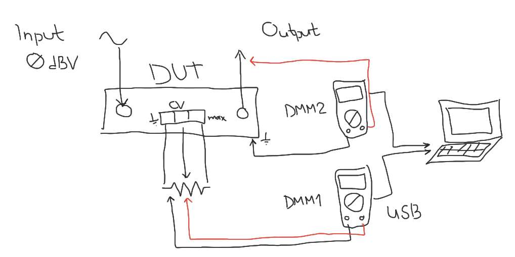
Agilent can display dBV levels by itself. Thus, by feeding the device under test with a sinewave at the reference level of 0 dBV, the reading of the multimeter on the output provides the device's gain directly. Then we can use log timestamps in order to establish correspondence between the controlling voltage and resulting gain. Note that because both the amplifier and the VCA unit accept balanced input, feeding them with unbalanced input—and that was what I did—decreases measured gain by half, that is by 6 dB. This is not relevant to the experiment because our intent is to measure both devices under the same conditions and compare their volume curves.
Using the approach above, I established that the amplifier goes from +24 dB down to -60 dB of gain, while the VCA unit goes from -6 dB down to -90 dB. Thus, the range of applied gains is actually similar, and is around 84 dB. However, the volume curves are totally different. In order to compare them, I've "normalized" the gain of the VCA unit, as if it were connected to a 30 dB fixed gain amplifier. Let's look at the shapes of the curves:

We can see that the volume of RU-VCA6A has a uniform slope (various bumps on it are likely due to imperfections in my measurement setup), whereas the volume curve of SPA4-100 has a linear region in the beginning up to about 2.5 kOhm resistance of the controlling pot, then it starts sloping, albeit slower than the curve of the VCA unit, and then at about 8 kOhm the amplifier basically drops the gain to the floor value of -60 dB.
Thus, it's not possible to achieve synchronous gain when using the same controlling pot for both devices. The fact that the VCA unit which controls the sub, lowers the gain at a faster pace than the amplifier for the main speakers leaves no hope to use nonlinearity of hearing—equal loudness curves—because they work exactly in the opposite way. And then I found yet another problem...
Noise and Distortion of the QSC VCA
As I started experimenting with the volume control on the QSC amplifier, I noticed that although the setup has practically no audible noise at the highest volume, the noise becomes audible as soon as I start turning the volume down. Normally, a power amplifier amplifies any noise fed to its input, and the higher the gain, the louder that noise will sound. The absence of noise at the highest volume proves that the noise from the DAC output is negligible low. Why does the noise starts appearing as we are making the gain lower?
I took some measurements of noise alone and of THD+N to demonstrate this phenomenon:


The blue FFT is taken at 2.5 kOhm, and the green FFT is at 3 kOhm of the controlling resistor value. The increase in noise and distortion is substantial and can be heard easily.
Now, looking at the volume curve of the amplifier, I've got the idea where does the noise comes from—it's from the amplifier's VCA unit which apparently has lower quality than the constant gain part. It seems that the VCA unit is bypassed when there is no attenuation. This explains the presence of the horizontal part on the volume curve. Once the volume control passes certain point, the VCA is engaged and the noise from it kicks in.
I guess, this was some sort of an engineering tradeoff. Understanding that not everyone really needs a volume control on a power amplifier, engineers at QSC provided a lower quality solution to save some money, however they were smart enough to get this lower quality VCA part out of the way on the critical path.
The Final Arrangement
Now for completeness, this is how my modular system looks after installing the QSC amplifier:

And this is the updated diagram of component connections:

Next time, I will finish this trilogy with a story about the digital part of the chain.
No comments:
Post a Comment